Logic Gates
Detailed Discussion
1)What are the Logic Gates ?
Logic gates are the basic building blocks of any digital circuit. A logic gate has finite number of inputs and only one output. The relationship between the input and the output is based on a certain logic. Based on this, logic gates are named as AND gate, OR gate, NOT gate etc.
AND Gate
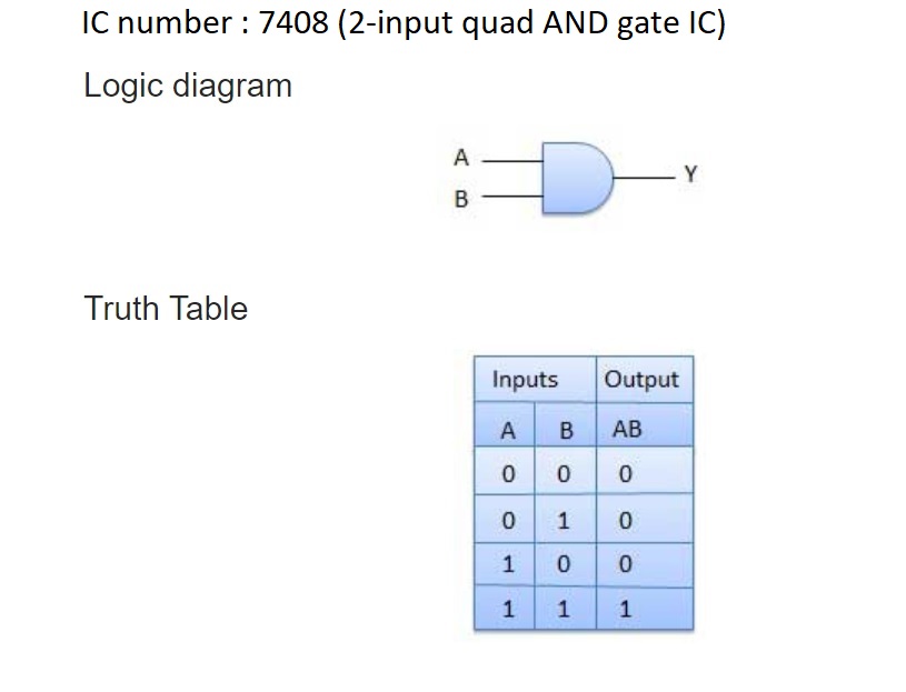
A circuit which performs an AND operation is shown in figure. It has n inputs (n >= 2) and one output. In AND gate the output of an AND gate attains the state 1 if and only if all the inputs are in state 1.
The Boolean expression of AND gate is Y = A.B, read as Y equals A ‘AND’ B.
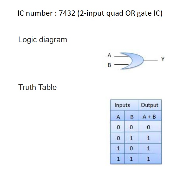
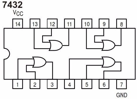
OR Gate
A circuit which performs an OR operation is shown in figure. It has n input (n >= 2) and one output. In OR gate the output of an OR gate attains the state 1 if one or more inputs attain the state 1.
The Boolean expression of OR gate is Y = A + B, read as Y equals A ‘OR’ B.
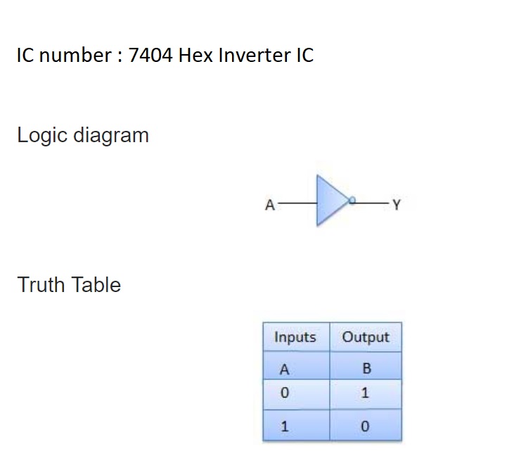
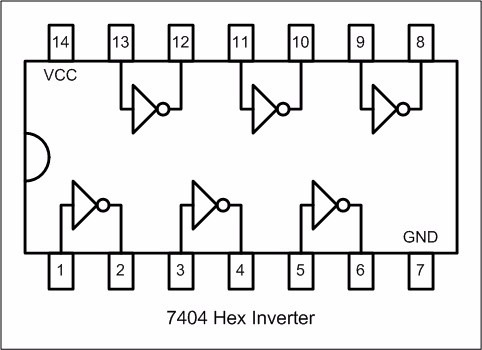
NOT Gate
NOT gate is also known as Inverter. It has one input A and one output Y. In NOT gate the output of a NOT gate attains the state 1 if and only if the input does not attain the state 1.
The Boolean expression is Y =  , read as Y equals NOT A.
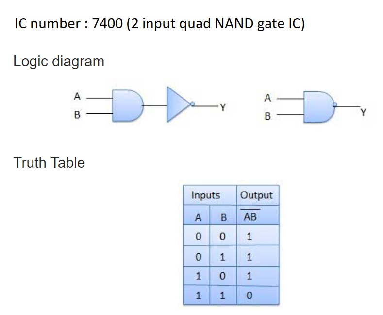
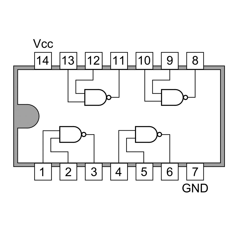
NAND Gate
A NOT-AND operation is known as NAND operation. It has n input (n >= 2) and one output.

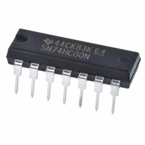
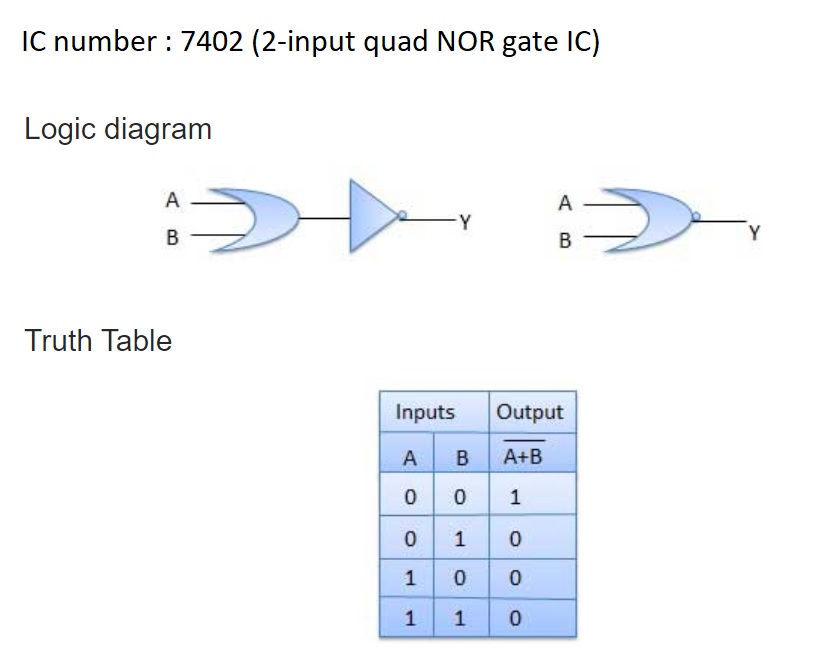
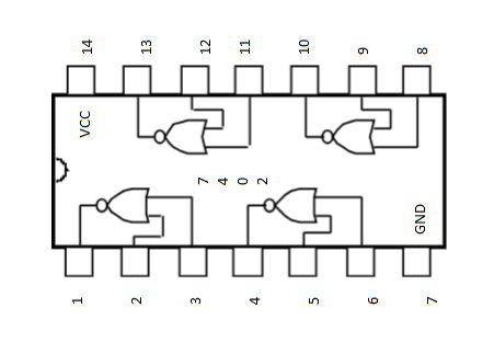
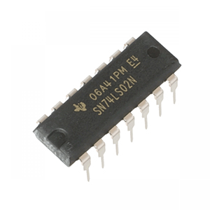
NOR Gate
A NOT-OR operation is known as NOR operation. It has n input (n >= 2) and one output.

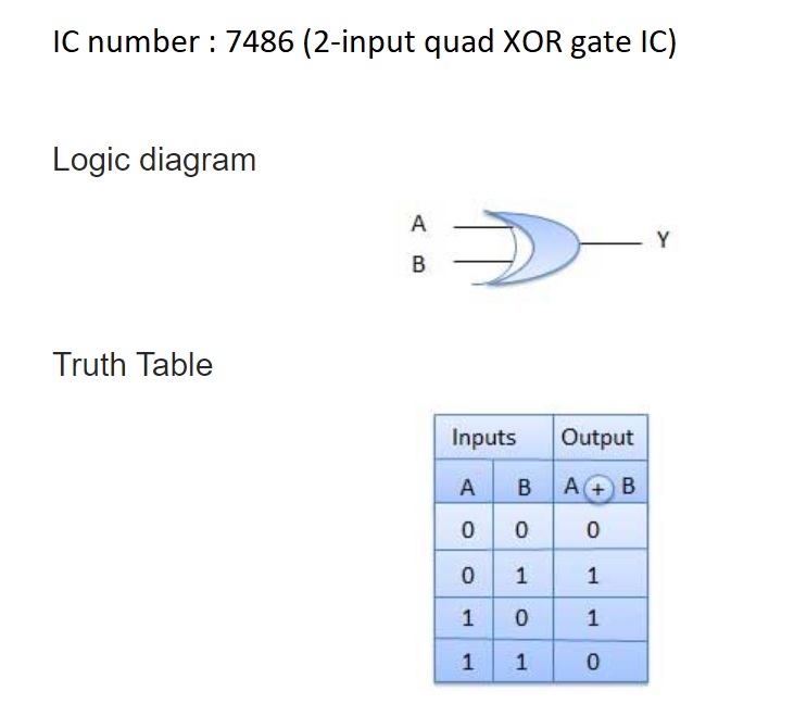
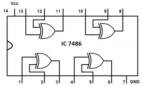
XOR Gate
The exclusive-OR gate is abbreviated as EX-OR gate or sometime as X-OR gate. It has n input (n >= 2) and one output. In XOR gate the output of a two-input XOR gate attains the state 1 if one adds only input attains the state 1.

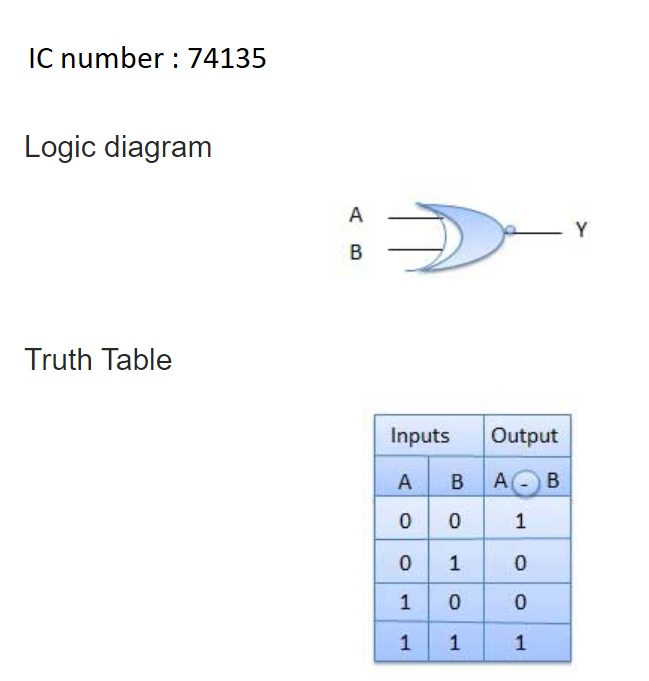
NXOR Gate
The exclusive-NOR gate is abbreviated as EX-NOR gate or sometime as X-NOR gate. It has n input (n >= 2) and one output. In XNOR gate the output is in state 1 when its both inputs are the same that is, both 0 or both 1.