Half & Full Subtractor Circuit
Detailed Discussion
1)What is a Half Subtractor Circuit?
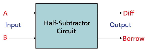
A half-subtractor is a combinational logic circuit that have two inputs and two outputs (i.e. difference and borrow). The half subtractor produces the difference between the two binary bits at the input and also produces a borrow output (if any).
Half Subtractor Block Diagram
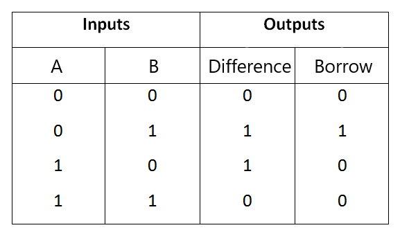
Half Subtractor Truth Table
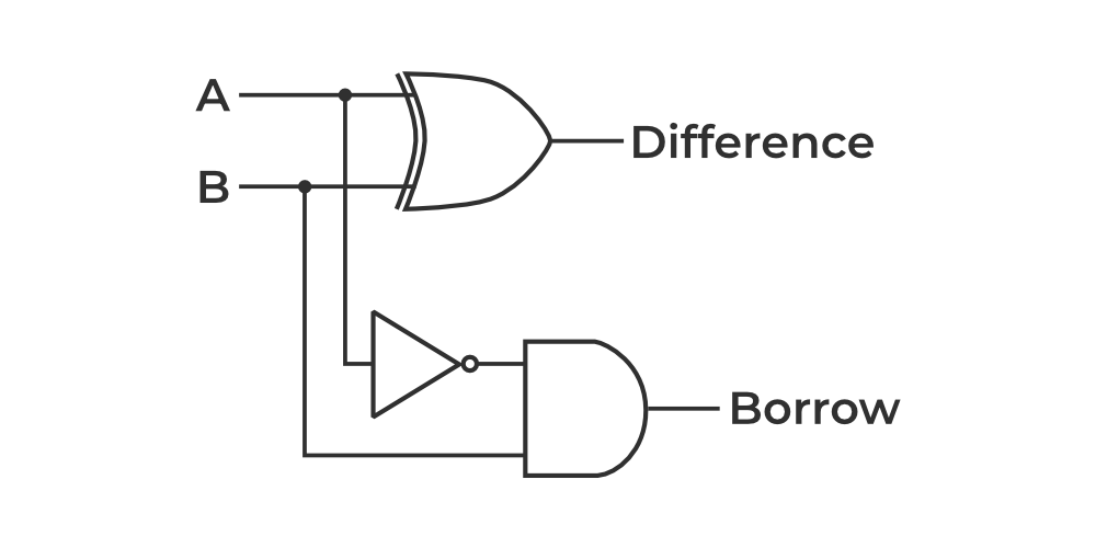
Half Subtractor Circuit/ Logical Diagram
1)What is a Full Subtractor Circuit?
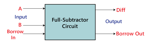
The Half Subtractor is used to subtract only two numbers. To overcome this problem, a full subtractor was designed. A full-subtractor is a combinational circuit that has three inputs A, B, C (B-in) and two outputs Diff and Borrow. Where, A is the minuend, B is subtrahend, C (B-in) is borrow produced by the previous stage, Diff is the difference output and Borrow is the borrow output.
As we know that the half-subtractor can only be used for subtraction of LSB (least significant bit) of binary numbers. If there is any borrow during the subtraction of the LSBs of two binary numbers, then it will affect the subtraction of next stages. Therefore, the subtraction with borrow are performed by a full subtractor.
Full Subtractor Block Diagram
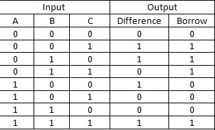
Full Subtractor Truth Table
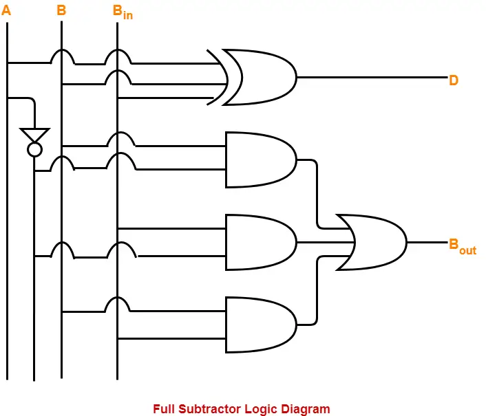
Full Subtractor Circuit/ Logical Diagram
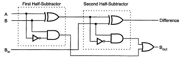
Full Subtractor using two Half Subtractor Block Diagram
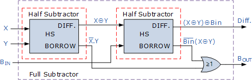
Full Subtractor using two Half Subtractor Circuit Diagram